The structure of a DC charging pile is composed of several critical components, including the power unit for converting AC to DC power, the control unit for monitoring and regulating the charging process, the metering unit for accurate billing, the charging interface for connection to electric vehicles, and various safety protection devices to ensure secure operation. The assembly and testing process involves meticulous steps such as component preparation, precise processing, and careful assembly. After assembly, the charging pile undergoes a series of rigorous tests, including voltage and current error tests, stability precision tests, protection function tests, and overall performance calibration to ensure high efficiency and safety. The production line is equipped with advanced automated equipment, such as assistive mechanical arms and automated carts, as well as intelligent systems for production management and equipment monitoring. These features enable efficient manufacturing and stringent quality control, ultimately delivering reliable and high-quality DC charging piles to the market.
Structure of a DC Charging Pile
The structure of a DC charging pile mainly consists of the following components:
1. Power Unit: This is the core component of the DC charging pile, typically referring to the DC charging module, which is responsible for converting AC power into the DC power required by the electric vehicle. It usually consists of a rectifier, filter, and transformer.
2. Control Unit: Also known as the charging pile controller, it falls within the scope of embedded hardware and software technology. It monitors parameters such as current, voltage, and temperature during the charging process and adjusts the working state of the charging pile based on these parameters. It can also communicate with the electric vehicle to monitor the charging progress in real time and provide necessary safety protection.
3. Metering Unit: Used to measure the amount of electricity during the charging process to ensure accurate billing.
4. Charging Interface: Connects the charging pile to the electric vehicle to transmit electrical energy and data. Common interface types include CHAdeMO and CCS.
5. Power Supply Interface: Connects to the power grid to provide the required AC power for the charging pile.
6. Human-Machine Interface: Typically includes a touchscreen or buttons for user operations, such as starting and stopping the charging process, setting charging parameters, etc.
7. Main Circuit: Responsible for processing the input and output of power, converting three-phase AC power into DC power, and then connecting to the charging gun to charge the electric vehicle.
8. Secondary Circuit: Includes the charging pile controller, card reader, display screen, DC electricity meter, etc., which are responsible for the control logic, user interaction, status display, and billing functions of the charging pile.
9. Safety Protection Devices: Include fuses, circuit breakers, lightning protection switches, residual current devices, etc., to ensure that power can be cut off in time in case of abnormal situations to protect personal and equipment safety.
10. Communication Module: May include WiFi or 3G/4G network communication modules for communication between the charging pile and the backend system to achieve remote monitoring and intelligent management.
11. Structural Design: The shell of the charging pile is usually made of corrosion-resistant and weather-resistant materials to adapt to outdoor environments.
Assembly and Testing Process of a DC Charging Pile
The assembly and testing process of a DC charging pile mainly includes the following steps:
1. Component Preparation
- Prepare the required components, including the charging pile body, power cables, sockets, electronic controllers, etc.
- Strictly inspect and screen the components to ensure their quality and performance meet the requirements.
2. Component Processing
- Process the components according to the design drawings, including machining, stamping, welding, and other processes to give them the required shapes and sizes.
3. Component Assembly
- Shell Processing and Assembly**: Process and assemble the shell of the charging pile.
- Power Module Installation**: Install the power module onto the charging pile body.
- Charging Module Installation and Wiring**: Install the charging module and make electrical connections.
- Display and Control Unit Assembly**: Install the display screen and control unit.
- Communication Module and Payment Module Integration**: Integrate the communication module and payment module.
- Internal Wiring Connection and Inspection**: Connect the internal wiring and conduct a preliminary inspection to ensure the connections are secure.
4. Testing and Debugging
- General Inspection: Inspect the appearance and installation of the charging pile shell and structural components.
- Output Voltage Error Test: Measure the output voltage error of the charging pile when it is in the constant voltage state to ensure the error does not exceed ±0.5%.
- Output Current Error Test: Run in the constant current state and measure the output current error to ensure it is within the specified range.
- Voltage Stability Precision Test: Measure the output voltage under different input voltages to ensure the voltage stability precision does not exceed ±0.5%.
- Current Stability Precision Test: Run in the constant current state and measure the output current value to ensure the current stability precision does not exceed ±1%.
- Current Limiting Characteristic Test: Test whether the charging pile can automatically reduce the output voltage to limit the increase in current when the output current exceeds the set value.
- Protection Function Test: Test the overvoltage, short-circuit, insulation grounding, and other protection functions.
- Withstand Voltage Test: Conduct a withstand voltage test on the AC input circuit and DC output circuit to ensure their withstand voltage performance meets safety requirements.
- Function Check: Test the charging setting methods, communication functions, display functions, input functions, metering functions, etc.
- Charging Output Test: Test the output voltage and current error, voltage and current stability precision, ripple coefficient, voltage and current limiting characteristics, efficiency, and power factor.
5. Appearance Treatment
- Conduct surface treatment and painting on the charging pile to enhance its appearance and quality.
6. Packaging and Transportation
- Package the charging pile to protect it from damage during transportation and label the packaging content and precautions.
Assembly Line for a DC Charging Pile
The assembly line for a DC charging pile usually includes the following sections:
1. Assembly Area
- Pre-assembly: Assemble the shell and internal structural components in the pre-assembly area.
- Module Installation: Install the charging modules, control systems, power interfaces, and display screens in sequence.
- Preliminary Testing: Conduct preliminary functional tests.
2. Pending Inspection Area
- General Inspection: Conduct visual inspections and basic functional tests on the charging pile.
3. Testing Area
- Withstand Voltage Test: Test the withstand voltage performance of the charging pile.
- ATE Automatic Testing: Conduct comprehensive automatic testing, including interoperability, protocol consistency, and electricity metering tests.
- Leakage Test: Test the air tightness of the charging pile.
- Final Calibration: Conduct comprehensive performance calibration of the charging pile.
4. Packaging Area
- Package the qualified charging piles for shipment.
Production Line Equipment
1. Conveyor System
- Use electric drum lines or chain plate lines, supporting frequency conversion speed regulation with a speed range of 10–30 m/min.
- Support gradual deceleration to ensure the product flow conforms to the production process.
2. Workstation Configuration
- Each workstation is equipped with control indicator lights, process tags, emergency stop buttons, toolboxes, sockets, and operating pedals.
- The first workstation is equipped with start/stop control buttons for the conveyor system and a workstation completion indicator light.
3. Automated Equipment
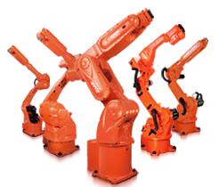
- Assistive Mechanical Arms: Used to lift the charging pile body, employing vacuum suction with a lifting capacity of more than 200 kg.
- Automated Carts: Used for offline transportation, capable of automated control along the designed route.
4. Testing Equipment
- Withstand Voltage Testing Equipment: Used to test the withstand voltage performance of the charging pile.
- ATE Automatic Testing Equipment: Used for comprehensive automatic testing.
- Leakage Testing Equipment: Used to test the air tightness of the charging pile.
5. Intelligent Systems
- The production line is integrated with intelligent systems, including production management systems and equipment monitoring systems.
- Supports interfaces such as RS485, LAN, and USB to meet various communication options.
- Equipped with CAN communication simulation modules to simulate vehicle BMS and test various response states of the charging pile.
Through the detailed descriptions of the structure, assembly and testing process, and assembly line of a DC charging pile, a comprehensive understanding of the production process of a DC charging pile can be obtained.
Factory address: East Industrial Cluster, Wenling City, Zhejiang Province
Aircraft: Taizhou Luqiao Airport (1 hour) Wenzhou Airport (2 hours)
High speed rail: Wenling Station (40 minutes)
Expressway intersection: Wenling North (15 minutes) Wenling East (20 minutes)
Contact our engineering team and get company info
Email: Assemblyline@qq.com


